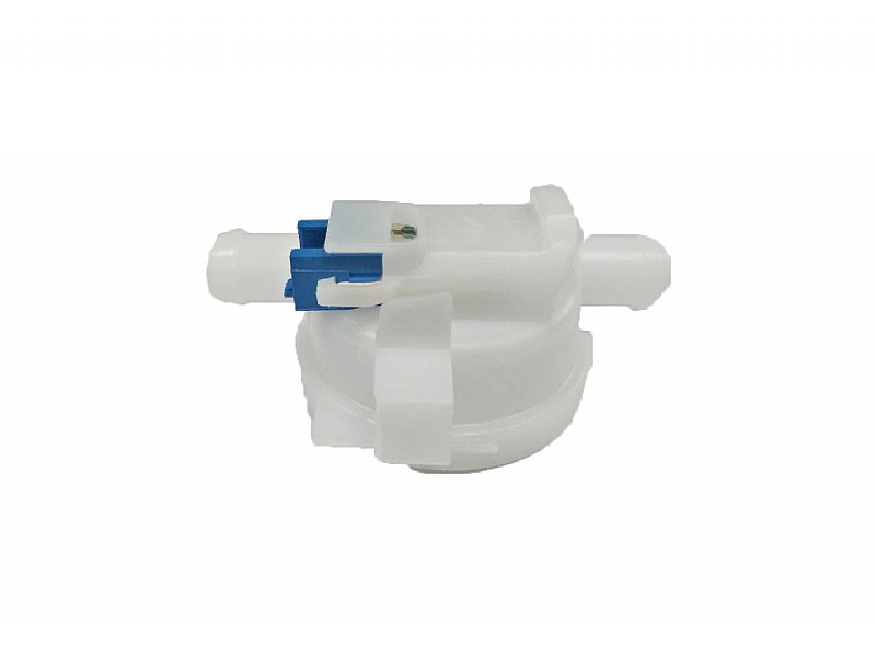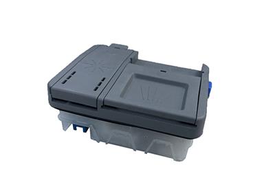
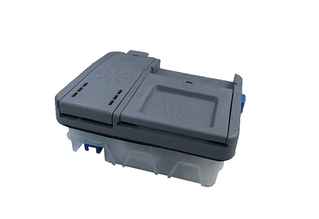
The dispenser is a supporting product of the dishwasher. It is used to realize the orderly delivery of detergent and rinse aid in the dishwasher. Smart reminder when there is no rinse aid in the chamber.
Application
It is used to realize the orderly delivery of detergent and rinse aid in the dishwasher. Smart reminder when there is no rinse aid in the chamber.
Specification
|
Item |
Name |
Specification |
Remark |
|
2. 1 |
Rated voltage |
AC220V |
Other voltage can be customized |
|
2. 2 |
Rinse aid storage volume |
135ml±10ml |
|
|
2. 3 |
Rinse aid to be delivered per time |
1.35ml ±0. 15ml |
|
|
2.4 |
Max delivery times |
6 |
|
|
2.5 |
Signal on |
50ml±15ml |
|
|
2. 6 |
Detergent chamber |
Detergen liquid 50ml |
|
|
3-in-1 washing block 20g |
|
Technical requirements
Start up test
Well install the dispenser in the dish washer, and apply 0.85 and 1.15 times the rated voltage to make the powder box open and the rinse aid sealing mechanism operate respectively. The test is repeated 5 times under different voltages. The powder box cover can be reliably opened, and the rinse aid can flow out smoothly every time without any abnormal sound.
3.2 Dshwashing powder and rinse aid requirements
3.2.1 When the solenoid valve is activated, the powder box cover must be able to open smoothly and the rinse aid can be delivered normally.
3.2.2 Under normal washing condition: before the powder box open, the dishwashing powder in the box cannot be agglomerated; after the powder box open, the dishwashing powder can leave the box completely.
3.2.3 Minimum rinse aid for reminder
Minimum rinse aid remaining: 50 ±15ml
3.3 Sealing performance test
Install the dispenser without power supply connection. Add dishwashing powde and run the strong-washing program until the dishwashing powder put-in procedure. Open the door to check the powder status in the chamber. Add the rinse aid to the dispenser. Put the dispenser into the oven vertically for 2h, with oven temperature 70~75°C, then place it vertically for 24h at room temperature. (Note that after adding the rinse aid, keep it horizontally for 60 seconds before placing it vertically to ensure that the rinse aid enters the dispensing chamber). Dishwashing powder and rinse aid must not leak.
3.4 Temperature rise test
Take the dispenser resistance before test as R1, then apply 1.06 times the rated voltage to the dispenser (placed as installed state), power on for 2 minutes (power on the machine for 1.5 minutes), power off for 3 minutes. After On and off for 3 hours, take the dispenser resistance as R2. Get the temperature rise At using the following formula. There is no abnormality during the test. The temperature rise meets the requirements of the drawing. The product can pass leakage current test, electric strength test and insulation resistance test 3 minutes after the temperature rise test.
公式***
式中:R1--- resistance before test,Ω
R2--- max resistance during test,Ω
Tl--- environment temperature before test,℃;
T2--- environment temperature after test,℃。
3.5 Vibration test
Fix the distributor on the vibration test bench。 Set the full amplitude to 1.5mm, the vibration frequency to 10~55~10Hz, 1 octave/min, vibrate for 45 minutes in each of the three axes (front and back, left and right, up and down) (10 cycles). After the test, it can pass the start-up test and sealing performance test, and the reed switch is not damaged.
6 Electrical strength test
1min after normal conditions and humidity condition, and 3 min after the temperature rise test, apply AC1500V, lmin between the conductive part and the non-charged metal part of the solenoid valve (the applied voltage is 1000V + 2UN after the humidity condition). During the test, there should be no breakdown or flashover, and the leakage current is less than 2.0 mA.
3.7 Insulation resistance
Use a DC500V insulation resistance meter to measure the insulation resistance between live parts and non-charged metal parts, insulation resistance ≥100MQ
3.8 Turn-to-turn withstand voltage test
Set the reference waveform from the turn-to-turn withstand voltage meter, and connect the two wires of the instrument to the solenoid valve terminal. Once entering the test state, press the start button to perform the test with voltage 1500V. The measured waveform is basically the same as the reference waveform.
3. 9 Terminal strength test
Solenoid valve terminal: apply a pulling force of 40N along the axis of the terminal for 10±ls; apply a force of 20N vertically to the axis of its leading end for 10 ± ls. Reed switch terminal: apply 20N along the axis of the terminal for 10 ± ls; apply 10N vertically to the axis of the lead-out end for 10 ± ls. After test, all terminals are not loosened or broken.
3.10 Self-locking overload test
The solenoid valve core is jammed on purpose. It is level with the inner hole of the coil. At 1.1 times the rated voltage, there is no fire or hot melt metal during working for 1 hour or before any abnormal conditions occur.
3. 11 Core pulling test
Pull out the solenoid valve core and fix the solenoid valve on test bench as per the installed state. The surrounding environment is not ventilated. There is no fire or hot melt metal during working (rated voltage) for 1 hour or before any abnormal conditions occur.
3. 12 Heat resistance, flame resistance and tracking test
The plastic in contact with the live part should be able to pass the flame resistance test and the 125℃ ball pressure test in Section 30.2 of GB 4706. 1 . For non-plastic encapsulated coils, the lead terminals should be able to pass the 2.50V tracking test.
3. 13 Constant humidity and temperature test
Set the constant heat and humidity box to temperature: 40±2°C, relative humidity: 93%±3%, and place the dispenser as the state of installation in the box for 48 hours. After the test, immediately apply a voltage of 1000+2UN for 1 minute. There should be no breakdown, and the insulation resistance is greater than 50MQ.
3. 14 Thermal shock test
Place the dispenser in an environment of -20±5°C for 2 hours, and then place it in an environment of 75±5°C for 2 hours. The conversion time is less than 3 minutes. Keep cycle working for 24 hours, then recover for 2 hours. After the test, the dispenser housing should not be damaged or deformed, and the dispenser can pass the sealing performance test, electrical strength test, insulation resistance test and start-up test.
3. 15 High temperature storage test
Place the dispenser in an environment of 75±5°C for 48h and recover it for 2h. The dispenser housing should not be damaged or deformed, and the dispenser can pass the sealing performance test, electrical strength test, insulation resistance test and start-up test.
3.16 Low temperature storage test
Place the dispenser in an environment of -20±5°C for 48h and recover it for 2h. The dispenser housing should not be damaged or deformed, and the dispenser can pass the sealing performance test, electrical strength test, insulation resistance test and start-up test.
3. 17 Salt spray test
Put the dispenser in a test environment with salt concentration 5% test temperature 35°C ±3°C for 48 hours. The metal parts are not rusty.
3. 18 Life test
3. 18. 1 Fix the dispenser in the life test fixture, at 1.06 times the rated voltage, set the parameters as follows: horizontal waiting time 10s, door closing time 10s, vertical waiting time 10s, door opening power-on time 10s, power-off time 30s, fluid power-on time 10s , Repeat 20,000 cycles.
3.18.2 Disassemble the reed switch from the dispenser and install it on the life test fixture, and let it operate repeatedly 10,000 times with a rated load at a frequency of 10-20 times/min.
For dispenser, no abnormality during the test, no damage after the test, no loosening of screws. The dispenser can pass the start-up test, sealing performance test, insulation resistance test and electric strength test. For reed switch, no abnormality during the test, no damage after the test. The reed switch can pass the insulation resistance test, electric strength test and contact resistance test, the seal parts must not fall off.
4. Packing and transportation
4.1 Packing
4.1.1 The dispenser should be wrapped in a proper method and placed in the box.
4.1.2 The packing box with the dispenser should be packed in a dry, moisture-proof, dust-proof and mildew-proof external box. The packing box should be tightly placed in the external box without shaking, and a PASS certificate should be placed in the external box.
4.1.3 The name, model, quantity, packager, date, inspection stamp, etc. of the product should be indicated on the packing box and external box. The external box should also comply with the corresponding transportation requirements specified in CB191.
4.2 Marks
There should be clear printing on each dispenser. The packing box and external box shall indicate the name, model, quantity, packager, date, inspection stamp, etc. of the product accordingly, and shall meet the requirements specified in GB191.
4.3 Transportation
The packed dispenser is allowed to be transported in any way, but it should avoid direct rain, snow or mechanical damage.
4.4 Storage
The packed dispenser should be at stored in a warehouse where the ambient temperature is -20~40°C and a relative humidity is no more than 80%, and no acid, alkali or other corrosive gas in the surrounding air.

Home appliance accessories, lightning protection appliances, product service providers
 Zhejiang ICP No. 05001732-1
  Shenlong official WeChat account